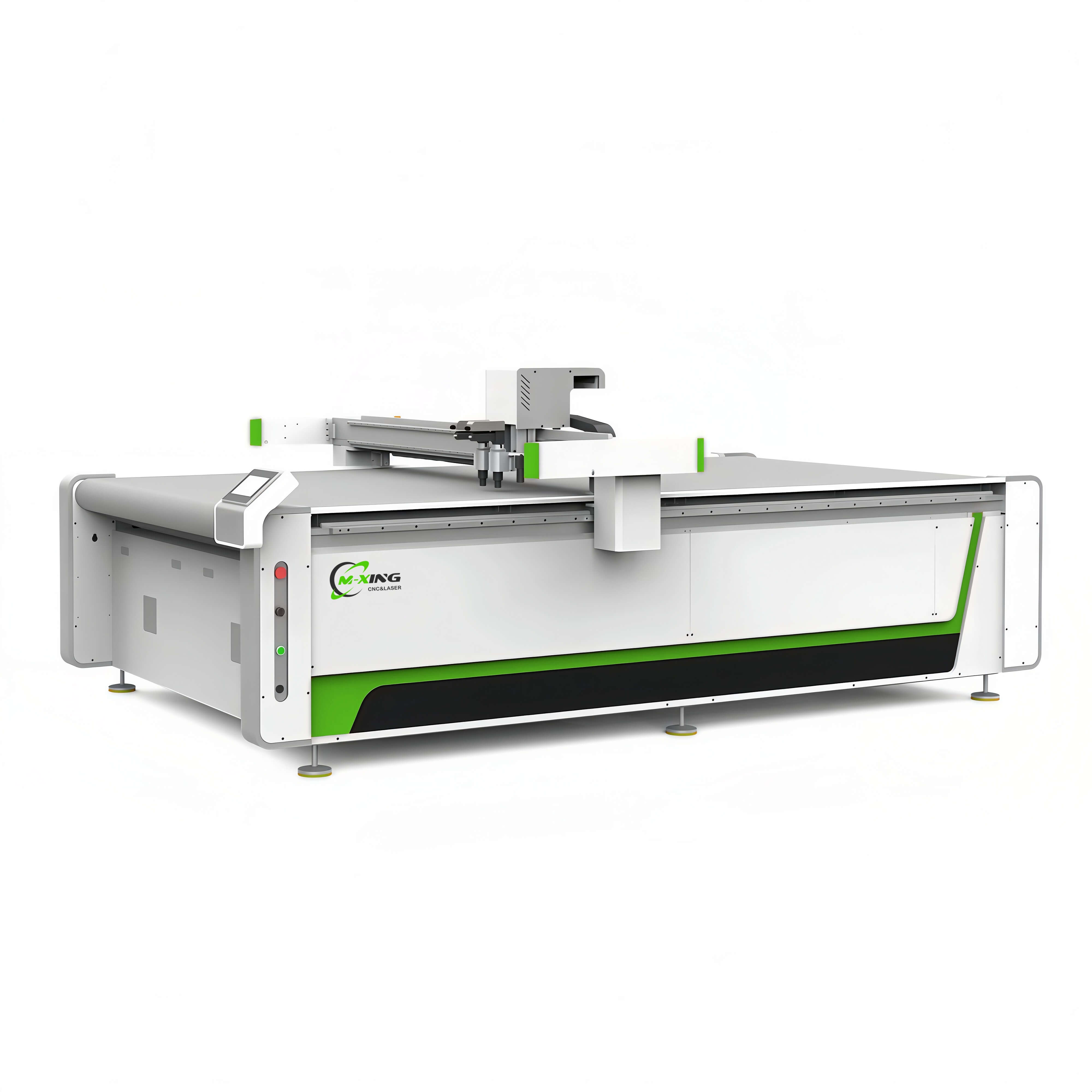
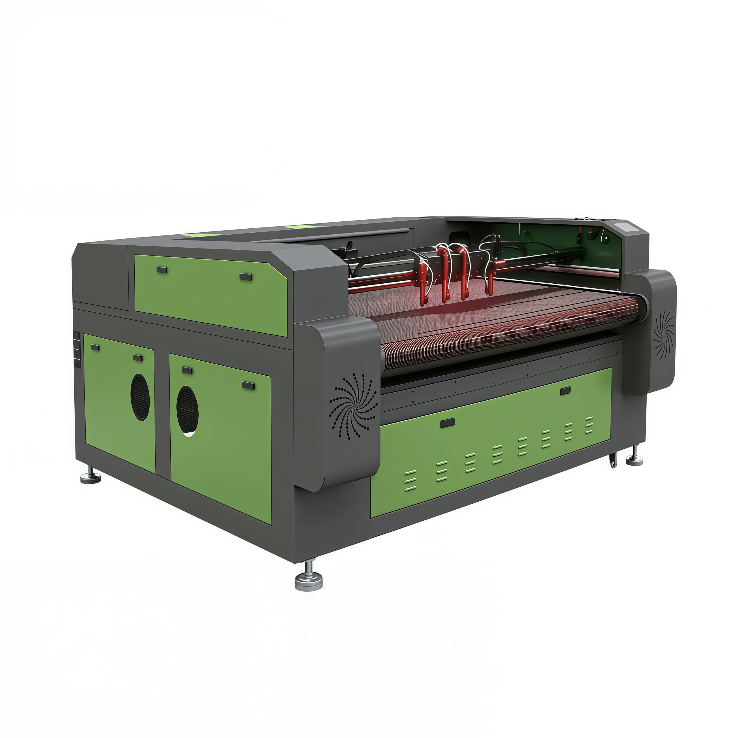
A laser cutter is blind. It trusts the file's coordinate origin and assumes the material is exactly where the drawing says it is. Every workaround operators use — squaring the sheet against stops, taping it down, cutting a test piece first — exists to make that assumption true.
A camera removes the assumption. It lets the machine see the actual sheet, find features that are already on it, and shift the toolpath to match. That is the whole function, and it is worth being precise about what it does and does not do.
It solves a positioning problem. It does not improve edge quality, cut speed or kerf. A camera on a badly focused machine produces a perfectly aligned, badly cut part.
Three different jobs get called "camera cutting", and they have different requirements:
Registration to existing marks. The material already carries fiducials, holes or edges. The camera finds them and offsets the file so the cut lands where it was designed to land.
Cut-to-print. The sheet carries printed artwork, and the cut must follow the print rather than the nominal drawing. This is the hardest of the three, because print is not rigid.
Nesting and remnant use. The camera maps what is actually usable on the sheet — the outline of an offcut, the position of a defect — and the operator nests parts inside that real area rather than a nominal rectangle.
A fourth, less discussed use is reverse digitizing: laying an existing part on the bed, tracing its outline on screen, and exporting a cut file. Useful for legacy parts with no drawing.
It is a common and expensive mistake to specify one camera for all of these, then judge it by the hardest one.
The tolerance that matters is not the camera's headline number. It is the tolerance of the assembly the part goes into, compared with the error the camera leaves behind at the corners of the bed, not at the centre.
The preview shows the artwork aligned to the cut lines. The job runs. Half the sheet is right and the other half has the cut walking off the print. This is the most common camera complaint, and the camera is usually not the cause.
Print is not a rigid body. Paper and board stretch and shrink with humidity. Laminates and films relax at different rates from the substrate they are bonded to. Screen printing can change the sheet's dimensions in the direction of the squeegee; digital print usually does not. Two sheets from the same box can differ. A printed sheet is therefore a slightly different size and shape every time — and not uniformly, but varying across the sheet and between sheets.
That is why a single offset-and-rotate cannot fix it. If the print has grown unevenly — more in the feed direction than across it, and more at one edge than the other — aligning three marks correctly still leaves the fourth area wrong. Cut-to-print needs local correction: several marks distributed across the sheet, with the software interpolating between them, or the sheet split into zones that are each aligned separately.
The rules that follow are simple:
A camera system has three calibrations, and each fails with a different signature.
Lens distortion. Every lens bends straight lines near its edges. Software corrects it with a model; if that model is wrong or missing, the centre of the image is accurate and the edges are not.
Scale. Pixels to millimetres. If the scale is wrong, dimensions are off by a percentage, and the error grows with distance from the reference point.
Camera-to-laser offset. The camera looks at a point that is not the nozzle. The distance between them must be known exactly, because every job is shifted by it.
Those three signatures are the fastest field diagnostic, and they are worth memorising:
Laboratory demonstrations use white paper and black dots. Workshops use glossy acrylic, dark leather, mirror-finish metal, busy printed artwork and transparent film. Camera detection is a contrast problem before it is anything else, and most on-site failures are optical rather than computational.
The countermeasures are unglamorous:
When detection fails intermittently, check in this order: mark contrast, mark size relative to the field of view, lighting consistency, window cleanliness, then software thresholds. Operators usually start at the last item.
A camera adds cost, a calibration burden and a per-sheet alignment step. It pays when a mis-cut sheet costs more than that step.
The honest calculation is per job family, not per machine: list the jobs where a sheet is expensive or the print dictates the cut, and see whether the saved scrap pays for the option.
Camera systems differ in ways that matter more than the brochure suggests, and the questions are worth asking before the order rather than after installation.
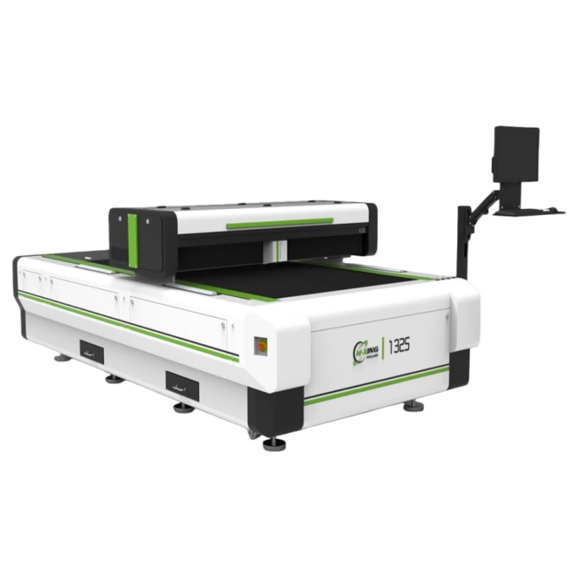
Is the camera fixed to the head or to the gantry? A head-mounted camera follows the cutting position and usually covers a smaller area at higher resolution; a gantry-mounted camera can capture a whole sheet but may stitch several images. Head-mounted favours registration to local marks; gantry-mounted favours full-sheet mapping and remnant nesting.
Can it see the whole bed, or does it stitch? Stitching works, but every seam is a place where alignment can drift. Ask how many images, and how long a scan takes on the largest sheet you intend to run.
What is the calibration procedure, and how long does it take? A calibration that needs a technician and half a day will not be redone when it should be. Ask for the routine and the tooling.
Does the software support multi-point alignment and remnant nesting? One-offset registration is a different product from zone-based cut-to-print. Check the workflow on your own file.
What does the accuracy figure refer to? Ask specifically: at the centre or at the corners, on what bed size, with what lens. A single headline number usually describes the best case.
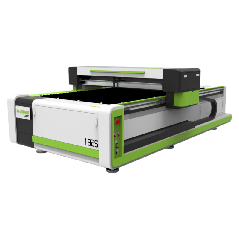
Mingxing Laser's 1325 platform is offered with an optional CCD camera for edge-patrol cutting, with Ruida and Xingduowei systems as options, alongside the standard 6090, 1390 and 1610 working formats. Whatever system is specified, the four-corner test is the only figure that describes what the machine will do on your material.
A camera is a positioning tool, and it is only as good as its calibration and its contrast. It will not rescue a wrong file, a wrong focus or a material that moves.
Used where it belongs — printed work, expensive sheet, remnant nesting, legacy parts — it turns a skilled operator's judgement into a repeatable routine, which is what a growing shop actually needs. Used as a substitute for process discipline, it produces scrap faster and with more confidence.
 Hot News
2026-02-05
2026-02-03
2025-12-01

Mingxing Laser is a leading China-based laser machine manufacturer offering CO2 laser cutters, fiber laser cutting machines, CNC routers, laser welders & marking machines. OEM/ODM custom solutions available. Get a quote today!
- Company Headquarters: Room 1303, Building 4, UnitedFortune Plaza, High-tech Zone, Jinan City, Shandong Province, China
- Manufacturing Plant: No. 18, Yinhe Road, Jibei Street, Jiyang District, Jinan City, Shandong Province, China
Copyright © 2026 Century Mingxing (jinan) Intelligent Technology Co., Ltd. All rights reserved. Privacy Policy

 EN