A drawing can be perfectly correct and the assembled part can still be loose, tight, or impossible to close. In laser cutting this is normal, and it has a specific cause: the beam removes material, so the cut is a slot rather than a line.
Three different errors get blamed for the same symptom, and separating them is the whole job:
Kerf. Systematic. The beam has width, so an outside contour comes out smaller than drawn and a hole comes out larger. It is predictable, repeatable, and compensable.
Machine and setup error. Backlash, belt tension, squareness, focus, a loose lens, a nozzle that is not perpendicular. This is not predictable and cannot be compensated in the drawing.
Material and drawing error. Thickness that is not what the drawing says, a sheet that is not flat, moisture swell, or a DXF that was drawn to nominal size while the part is meant to be a press fit.
Fit problems are usually kerf plus one of the other two. Compensating for kerf on a machine with backlash simply hides one error inside another, which is why the measurement step matters as much as the offset step.
Kerf is the width of material the beam destroys along the cut. It is often treated as a fixed property of the machine, quoted once and reused forever. That is the source of most fit failures.
What actually changes kerf:
The practical consequence is that kerf belongs to a material + thickness + process combination, not to a machine. A number measured on 3 mm plywood tells you nothing about 10 mm acrylic, even on the same bed with the same lens.
Kerf is also not symmetric. On thicker material the cut is tapered: the entry is wider than the exit, or the reverse depending on focus. A single kerf value describes the average, which is why thick-material joints need a test piece rather than a formula.
There are two reliable ways to get the number, and one unreliable one.
The outside-contour method. Cut a square of known nominal size along its drawn outline, then measure the finished part. Because the beam follows the line and removes half a kerf on each side, the part comes out smaller than nominal by one kerf. Subtract the measured size from the nominal size and you have the kerf.
The inside-contour method. Cut a hole or slot of known nominal size and measure it. The hole comes out larger than nominal by one kerf, for the same reason in reverse. If the two methods disagree noticeably, you are seeing taper, and the material is too thick for a single value to be honest.
The unreliable way is to cut one part, decide it is "a bit loose", and dial the offset until it feels right. That produces a number that works for that part on that day and fails on the next batch, because it folds machine error, material variation and operator judgement into what should be a measured constant.
Measure three to five samples from the same sheet, at the settings you will actually run, and record the average plus the spread. The spread is as useful as the average: if it is wide, the process is unstable and no offset will fix it.
For joints that must fit together, the most honest test is the joint itself. Cut a small comb of tabs and slots across a range of clearances, assemble them, and keep the one that matches the required feel. That single test piece settles more arguments than any calculation.
Kerf compensation is applied to the toolpath, and the direction depends on whether the contour is an outside edge or a hole.
Outside contours move inward by half the kerf, so the finished part reaches nominal size. Holes and inside contours move outward by half the kerf, so the finished hole reaches nominal size.
The most common software error is a factor-of-two mistake. If the compensation field expects half the kerf and the operator enters the full kerf, every part is undersized by half a kerf — and every hole is oversized by the same amount. The symptom is consistent across the whole sheet, which is the clue that it is a convention problem and not a machine problem.
Tab-and-slot joints need compensation on both sides. The tab is an outside contour and the slot is an inside contour, so the gap between them is the sum of two half-kerf offsets. If only one side is compensated, the joint will be consistently tight or consistently loose depending on which side was missed.
Press fits need a deliberate negative clearance. Kerf compensation brings the parts to nominal; it does not create interference. If the design calls for a press fit, add the interference allowance on top of the compensation, and test it, because the amount that feels right depends on the material.
Adhesive joints need room for the glue line. Compensating exactly to nominal leaves no gap for adhesive, and a starved glue line fails quietly.
Nesting software is usually judged on material yield. Yield matters, but nesting also decides whether the parts come out the right size.
Cut sequence changes accuracy. If all outside contours are cut first, parts lose their connection to the sheet and can shift before their inner features are cut. Cutting inner features first, or leaving small bridges until the end, keeps every part located until it is finished.
Tight nesting concentrates heat. Grouping many parts into one area raises the local temperature, and thin sheet, acrylic and foam all move when they get hot. A layout that saves a few percent of material but produces dimensional drift in the middle of the sheet is a net loss.
Grain, extrusion direction and flute direction are orientation constraints. Wood grain affects appearance and strength; extruded acrylic behaves differently along and across the extrusion; corrugated board has a flute direction that changes both cut quality and box strength. A nesting engine that ignores orientation will produce parts that fit but do not behave as designed.
Common-line cutting is efficient and unforgiving. Sharing one cut between two adjacent parts saves a pass and a kerf, but both parts then depend on that single line, and each loses material on one side only. If the line drifts, two parts are wrong instead of one.
Bridges and tabs keep the sheet together. Leaving small uncut tabs holds parts in place through the job and prevents them from tipping into the path of the head. They cost a few seconds of trimming and prevent a whole category of scrap.
If compensation is correct and the parts still do not fit, the cause is usually one of a small number of things, and each has a distinct signature.
Two of these are worth memorising because they are so common. A unit mismatch produces a constant ratio error, which is unmistakable once you look for it. A half-versus-full offset error produces a constant absolute error across the whole sheet, and it is the reason a shop can cut beautifully for months and then suddenly "lose accuracy" after someone edits a setting.
Kerf knowledge usually lives in one operator's head, which makes it a business risk rather than a technical detail.
A practical library is a table with one row per proven combination: material, supplier and batch, thickness, lens, focus, power and speed, measured kerf at top and bottom, date, and the machine it was measured on. Nothing about it is sophisticated, and it converts a skilled guess into a repeatable process.
Re-measure when any of the following changes: a new material batch or supplier, a lens or nozzle change, a tube replacement, a focus change, a belt or rail service, or a change in the number of passes. Those are exactly the events after which a shop reports that "the machine lost accuracy" — the machine rarely did.
The library also has a commercial use. Kerf changes material yield and fit, so quoting from measured data rather than from a catalogue assumption protects the margin on repeat orders.
When parts must fit, the specification that matters is not the headline accuracy figure but repeatability — the ability to return to the same position, job after job, after the machine has warmed up, cut for six hours, and been reused the next morning.
Three machine characteristics support that:
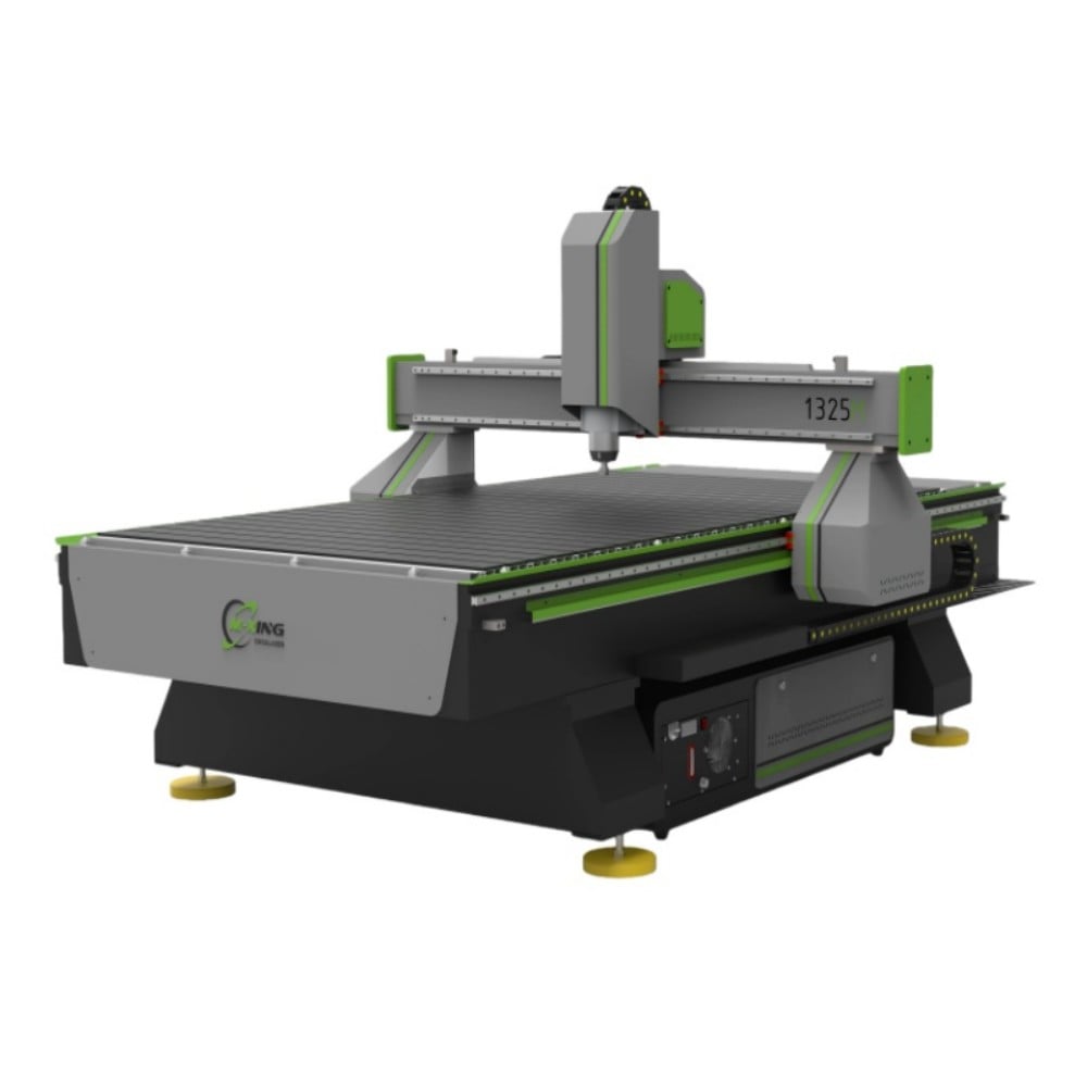
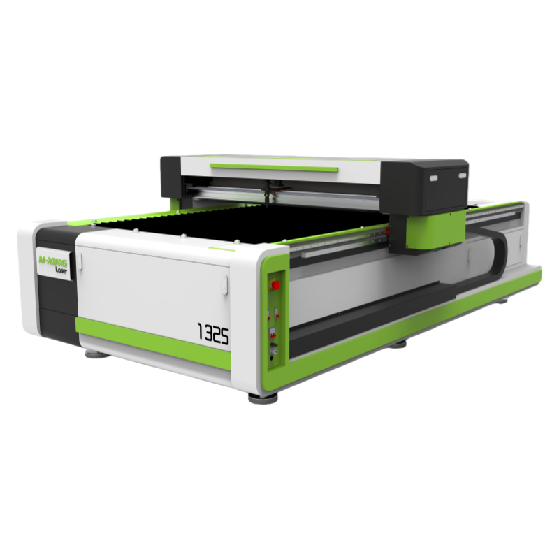
Motion system stiffness and stability. A gantry that flexes under acceleration produces errors that vary with direction and speed, which is precisely the error that cannot be compensated in a drawing. Linear-motor and magnetic-levitation platforms exist for this reason: the published 1325 magnetic levitation specification states a 0.05 mm repeat accuracy at up to 1 m/s travel, which is the combination that matters for production fitting work rather than for a single slow test cut.
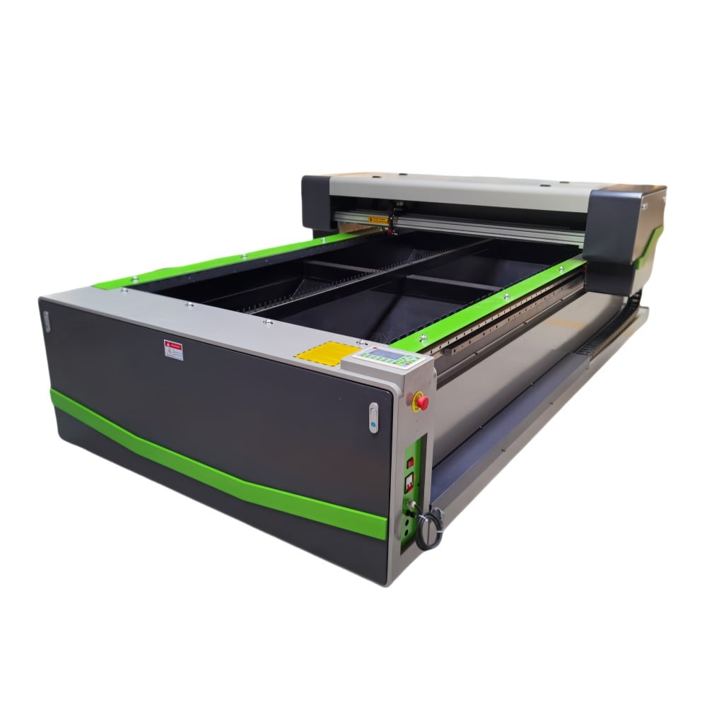
Consistent beam delivery across the bed. Constant optical path designs keep spot size and kerf consistent from one corner of a large sheet to the other. On a 1300 x 2500 mm bed, a kerf that changes across the sheet turns into a fit that changes across the sheet.
Bed size versus thermal stability. A larger bed allows better nesting yield, but it also means longer cuts and more opportunity for thermal drift. Zoning the cut sequence matters more on 1325 and 1610 formats than on a 6090, where a single sheet is usually completed before heat becomes a factor.
Camera registration is the other accuracy tool worth naming: when parts must align to printed artwork rather than to a sheet edge, a camera system removes the cumulative error of manual alignment. That is a different problem from kerf, and it is often confused with it.
Fit is not a matter of luck or of buying a more accurate machine. It is a short, auditable chain: measure kerf on the material you are about to cut, apply half of it in the correct direction on both sides of every joint, nest so that parts stay located and do not overheat, and keep a record so the next operator does not start from zero.
The shops that never seem to have fit problems are rarely using better machines. They are using a test piece, a caliper, and a table of numbers that someone bothered to write down.
 Hot News
2026-02-05
2026-02-03
2025-12-01

Mingxing Laser is a leading China-based laser machine manufacturer offering CO2 laser cutters, fiber laser cutting machines, CNC routers, laser welders & marking machines. OEM/ODM custom solutions available. Get a quote today!
- Company Headquarters: Room 1303, Building 4, UnitedFortune Plaza, High-tech Zone, Jinan City, Shandong Province, China
- Manufacturing Plant: No. 18, Yinhe Road, Jibei Street, Jiyang District, Jinan City, Shandong Province, China
Copyright © 2026 Century Mingxing (jinan) Intelligent Technology Co., Ltd. All rights reserved. Privacy Policy

 EN